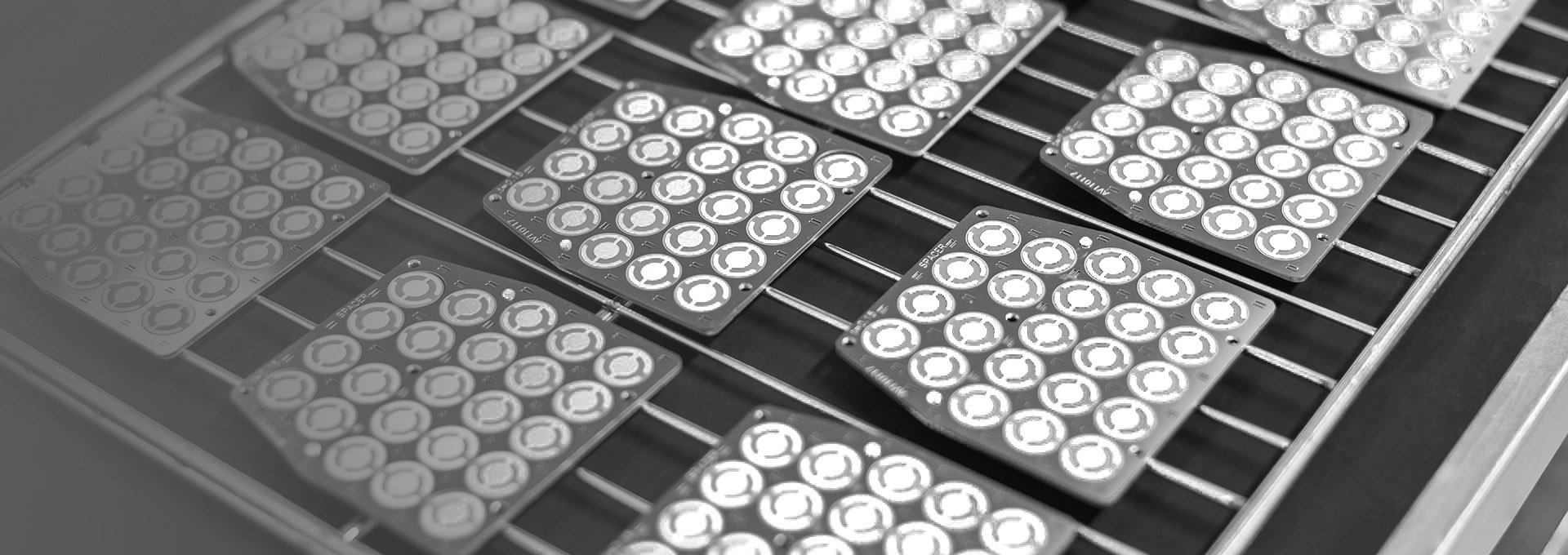

Small Quartz Crystal, A Key Factor Affecting Coating Yield
Coating practitioners working in optics, magnetron sputtering, or electron beam evaporation — when facing inaccurate film thickness, rate jumps, or poor batch consistency, 90% of people first adjust processes or check equipment, but easily overlook the most critical precision component — the quartz crystal. Today, combined with INFICON original technical data, we will dissect the working principle, failure mechanism, electrode selection, and practical guide to help you select and use the right crystals, stabilize yield, and reduce overall costs.
1. Working Principle of Quartz Crystals: Piezoelectricity + Mass Loading
1.1 Piezoelectric Effect — Making Quartz Vibrate at High Frequency
The substrate of a quartz crystal is a quartz crystal, i.e., silicon dioxide. When an alternating current (alternating electric field) is applied, it vibrates at high frequency like a tuning fork, emitting an extremely stable "sound" (electrical signal).
💡 Analogy: Like running your finger around the rim of a wet glass, the glass produces a clear, fixed-pitch sound. The quartz crystal is an electrically driven "super tuning fork."
2.1 AT-Cut Quartz Provides Stability
During coating, the chamber temperature changes. If the crystal's frequency drifts due to thermal expansion, thickness measurement becomes inaccurate. This is where the AT cut proves its value.
AT cut is the most common quartz crystal cut — cutting along the X-axis, rotated 35°15' from the Z-axis. The resulting wafer has a unique feature: in the common coating range of 25°C to 125°C, the vibration frequency is almost unaffected by temperature, with extremely low temperature drift.
In other words, although the chamber temperature changes, the AT-cut quartz crystal "remains unmoved," keeping the frequency stable, and thus thickness measurement remains accurate.
This is why AT cut is the most widely used solution today — proposed in 1933 by Dr. Isaku Koga and Dr. Noboru Takagi (called R1 cut at the time), it still plays a core role in thickness monitoring.
3.1 Why is it the "Ideal Choice for Film Thickness Monitoring"?
| What Coating Monitoring Needs | Can Quartz Meet It? |
|---|---|
| Extremely stable vibration frequency | ✅ Piezoelectric effect is inherently stable |
| No interference from temperature changes | ✅ AT-cut temperature drift ≈ 0 |
| No film contamination in vacuum | ✅ Quartz is chemically inert |
| Can sense extremely thin films | ✅ Accuracy down to Angstroms |
Other materials either "drift" at high temperatures or outgas in vacuum, contaminating the film — none can be as "versatile" as quartz.
4.1 Mass Loading Effect — How Quartz Crystals "Weigh" Film Thickness
Core Principle
A quartz crystal comes from the factory with a fixed fundamental frequency (commonly 5MHz or 6MHz), just like a tuning fork has a fixed pitch.
| State | What Happens | Frequency Change |
|---|---|---|
| Bare wafer | Clean wafer vibrates | = Fundamental frequency (e.g., 6.000000 MHz) |
| During coating | Coating material atoms "land" on the crystal layer by layer | The crystal becomes "heavier" and vibrates slower |
| After coating | Crystal mass increases | Frequency decreases |
💡 Analogy: Like a guitar string — the thicker and heavier the string, the lower the pitch. Deposition = "thickening" the crystal, so frequency drops.
Why can thickness be calculated?
The instrument internally converts: Frequency drop ∝ Film mass Film mass = Film thickness × Material density
So the instrument only needs to know:
- How much the frequency dropped (real-time measurement)
- The material density (pre-entered)
to calculate in real time:
- How thick the film is (thickness)
- How much is deposited per second (rate)
Summary
A quartz crystal is like a tiny electronic scale. Deposition makes it "heavier and slower," and the instrument calculates "how thick it is" from "how much slower it became" — this is the mass loading effect.
2. Quartz Crystal Selection Guide
2.1 Classification of Quartz Crystals: By Electrode Material
In thin film deposition processes, the quartz crystal is the core component for thickness monitoring. Different processes and materials have different requirements. The core difference lies in the electrode material — choosing the right electrode ensures accurate measurement, stable process, and controllable cost.
Golden rule: Choose the most suitable, not the most expensive.
Below are three mainstream quartz crystals classified by electrode material and their application scenarios.
1. Gold-Coated Quartz Crystal (Au Electrode)

Advantages:
- Extremely strong chemical stability, almost no reaction with the environment
- Infinite shelf life (no oxidation)
- Low contact resistance, stable signal transmission
- Low rate noise, smooth measurement
Applicable processes/materials:
- Low-stress metal films such as Al, Au, Ag, Cu
- General optical AR coatings (anti-reflection coatings)
Disadvantages:
- Prone to film peeling when encountering high-stress dielectric films or high-stress metal films
- Short lifespan under high-stress process conditions
Suitable for most conventional metal coatings and general optical films — the most versatile choice.
2. Silver-Coated Quartz Crystal (Ag Electrode)
Positioning: Dedicated for high-temperature/sputtering processes Advantages:
- Highest thermal conductivity among all electrode materials
- Fast heat dissipation, strong thermal shock resistance
- Outstanding stability in magnetron sputtering and high-temperature environments
Applicable processes/materials:
- High-stress metal films such as Ni, Cr, Ti
- Magnetron sputtering processes
- High-temperature coating environments
Disadvantages:
- Silver easily reacts with sulfur in the air (tarnishes black)
- Must be stored in dry, sealed conditions
- Recommended to use within 6 months after opening
Suitable for high-energy, high-temperature processes, but has higher storage requirements.
3. Silver-Aluminum Alloy Quartz Crystal (Ag-Al Electrode)
Positioning: The king of optical dielectric films Advantages:
- Highest hardness, dense surface
- Strongest stress dispersion capability
- Maximum sputtering and thermal shock resistance
- Excellent match for high-stress dielectric films
Applicable processes/materials:
- Optical dielectric films such as SiO₂, TiO₂, OS50, MgF₂, AlN
- Precision filters
- Multi-layer AR coatings
Disadvantages:
- Slightly higher cost than ordinary materials
- Not suitable for recycling
For optical coating processes with extremely high quality and stability requirements, the Ag-Al crystal is the top choice.

